|
The À Trous Wavelets Window |
|
|
|
Layer parameters summary list box Current layer parameters controls Predefined wavelet scaling functions Filter Management dialog (available through the Manage button) |
|
|
|
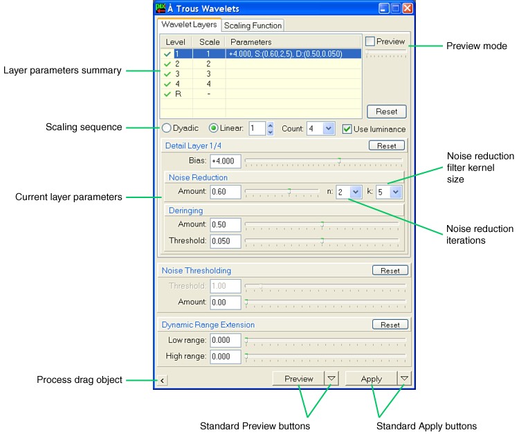
This window is the standard interface for ATrousWaveletTransform.
In this tab sheet you'll find a rich set of controls designed to adjust every parameter related to the layered wavelet decomposition performed by the ATrousWaveletTransform process. This includes both the global layering and the individual layer sets of parameters.
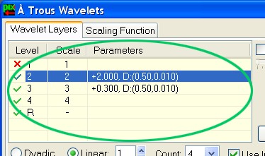
Each line in this list box corresponds to a wavelet layer. Layers are generated according to the currently selected scaling sequence and layer count parameters. The selected line in this list (shown as a blue line on the figure above) corresponds to the current layer, whose parameters can be edited in the current layer parameters section. Detail layers are numbered starting from 1. The last residual layer is always generated, regardless of the scaling sequence parameters used, and is denoted by 'R'. Individual layers can be enabled or disabled. To enable/disable a layer, double-click on the first column of the corresponding line, entitled as "Level". When a layer is enabled, this is indicated by a green check mark. Disabled layers are denoted by red 'x' marks. Note that the set of bias, noise reduction and deringing parameters is summarized in this list. With a little practice you'll easily get a precise idea of the entire wavelet process by just having a look at this parameters summary.
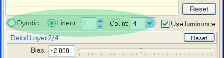
These controls allow you to specify a scaling sequence for the wavelet decomposition process. You can select either dyadic or linear sequence. The dyadic sequence uses increasing powers of two as the scale ranges for successive layers, that is, the 1, 2, 4, 8, ... sequence. Linear sequencing can range from 1 to 16. For example, if you choose Linear 1, the sequence 1, 2, 3, ... will be used. If you choose Linear 5, the sequence 1, 6, 11, ... will be used. Use the Count drop-down list to specify how many detail layers will be generated. You can work with a minimum of one up to a maximum of twelve detail layers. Take into account that more detail layers means more processing time and, if very large dimensional scales are used, a significant amount of memory required to complete the wavelet transform.
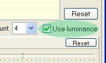
The Use luminance option, which is selected by default, will cause the process to be applied to the luminance of a color target image exclusively. For grayscale images, this option is simply ignored. Luminance/chrominance separations are performed in the RGB working space of the target image. In general, for strict noise reduction purposes, you'll want to unselect this option when working with color images, since otherwise chrominance noise will not be reduced at all. For detail enhancement, however, applying ATrousWaveletTransform to the three color channels of an image is a naive, mostly incorrect procedure.
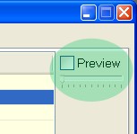
The À Trous Wavelets window can work in two different modes: processing mode and preview mode. In processing mode, the normal à trous wavelet transform is carried out. The normal mode should be active when you preview or apply an ATrousWaveletTransform process for effective image processing. In preview mode, the À Trous Wavelets window defines a special process instance that can be used to investigate which structures are contained by individual wavelet layers. To activate the preview mode, check the Preview check box and select the desired layer. Then execute the ATrousWaveletTransform on a preview object. If you are using a color target image and the Use luminance option is selected, then you should select the luminance display channel on the target image window for the previewed wavelet layers to make sense. Don't forget to unselect the preview mode once you're ready to effectively apply the ATrousWaveletTransform process.
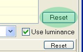
This button clears the whole set of parameters for all of the wavelet layers currently defined. Be careful since Reset cannot be undone.
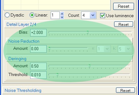
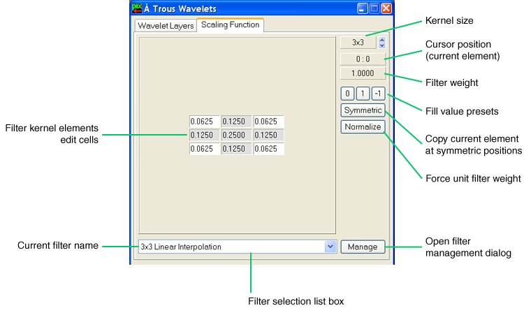
This section comprises a set of controls designed to fine-tune layer-specific parameters: bias, noise reduction, and deringing. See the corresponding specific documentation sections by following the preceding links, or read the entire section on the ATrousWaveletTransform process. With the information given on these sections, the current layer controls are self-explanatory. Noise reduction parameters number of iterations and filter kernel size are governed by the combo boxes labeled n and k, respectively. Scaling Function tab sheet The figure below shows the Kernel Filter Editor embedded in the À Trous Wavelets window. This filter editing system is a common interface resource in the PixInsight environment. For example, it can be found also embedded in the Convolution window of PixInsight Standard, and user-defined modules can embed it in their own interface elements. To access the filter editor on the À Trous Wavelets window, select the Scaling Function tab sheet.
The filter editor allows you to select a scaling function that will be used by the à trous discrete wavelet transform algorithm. This scaling function plays a crucial role by determining how specific dimensional scales are isolated into individual wavelet layers. See the documentation section dedicated to wavelet scaling functions. The filter editor allows you to manage a filter set. A filter set includes one or more kernel filters stored on a special disk file that we call a filter set module. Filter set modules use a proprietary file format and carry the ".pi-fsm" file extension. Eventually, the pi-fsm file format specification will be made publicly available; however, there are no plans to do so as of the date of release. With the filter editor you can manage a filter set by defining, deleting, replacing and renaming your own functions at your will. You can save and retrieve filters to/from pi-fsm files without specific limits.
PixInsight LE 1.0 comes with a small set of predefined, commonly used wavelet scaling functions. Included in the default set are the following functions:
This comprises the largest portion of the filter editor. Each cell allows you to enter a real number as the value of the corresponding filter kernel element. You can navigate through edit cells by clicking them with the mouse or by using the Tab and Shift-Tab keys. Kernel filter elements for ATrousWaveletTransform are allowed to have values in the range -100 to +100. Zero elements are shown empty for visual simplification. The à trous wavelet transform algorithm needs a low-pass filter as a scaling function to work properly. For this reason you usually should not enter negative values as filter elements. However, our interface implementation does not impose restrictions in this sense because certain applications can use some negative values for special purposes. In the same way, you are not required to define a symmetric filter; for normal applications, however, wavelet scaling functions should be symmetric.
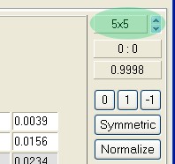
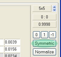
Here you can read and change the size of the square kernel filter. Kernel filters must be odd-sized to guarantee the existence of a unique central element. The minimum possible size is three, and the maximum allowed size is eleven for ATrousWaveletTransform. Most usual scaling functions are 3x3 and 5x5 kernels.
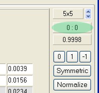
This panel shows the coordinates of the current edit cell, i.e. the cell that has focus. Coordinates are integer numbers shown as horizontal:vertical. The central element has coordinates 0:0. Horizontal coordinates increase from left to right. Vertical coordinates increase from top to bottom (the same coordinate system used for images by default).
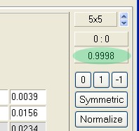
The filter weight is the sum of all the filter elements. A filter is called normalized when the absolute value of its weight is equal to one. The filter weight should always be positive and nonzero to get meaningful wavelet decompositions.
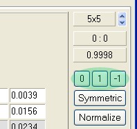
With these buttons you can set all of the filter elements to zero, one, or minus one.
Click this button to copy the current element to symmetric filter locations. For example, if you are editing the top left element of a 3x3 filter, Symmetric will copy it to the remaining three corner elements.
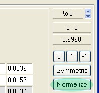
This is used to obtain a normalized filter equivalent to the current filter. By clicking this button you force the filter weight to be equal to one, or minus one, depending on the sign of the current filter weight. For example, if you have a 3x3 filter with all of its elements equal to one, normalizing it would replace every filter element with 0.111..., to sum up exactly one.
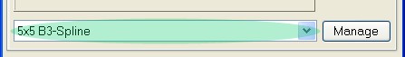
Use this combo box to select a particular filter from the current filter set. You can select a predefined wavelet scaling function, or you can define and use your own functions. There is also a special item on this combo, namely "<* New Filter *>", that you can use if you want to start defining a new scaling function from scratch.
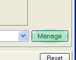
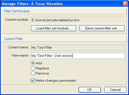
The Manage button opens the Filter Management dialog box. You have an example on the figure below.
As you see, you can change the current filter set module in use for the client window (the À Trous Wavelets window in this case) with the Load... button. You can save the current filter set module to another disk file with the Save... button. On the example above, the default filter set module file is being used, namely atw-default.pi-fsm. When you are editing a new filter, you have the Add, Replace and Remove options available. You can type in an identifying name for the current filter. If you use an already existing name, the filter manager will automatically append an increasing number to make the filter name unique. If you leave the name blank, the filter manager will assign a default filter name for you. With certain filters you cannot make changes. This is done to ensure that a default filter set is preserved, as a way to protect you from yourself. In these cases both Replace and Remove buttons are disabled. With the Make changes permanent check box you can choose whether to write changes to the filter set module file or not. If you choose not to write, changes will be lost upon program termination or if you select a new filter set module file.
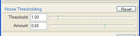
This section allows entering noise thresholding parameters: noise threshold and thresholding amount. A zero amount value disables noise thresholding. Noise thresholding is disabled by default.
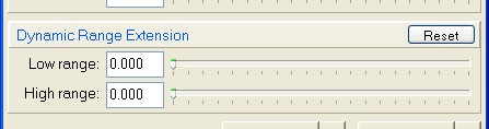
Use the controls in this section to adjust dynamic range extension parameters. A zero range value disables the corresponding extension feature. Dynamic range extension is disabled by default. |